The crane
The stacking crane is an extension and is meant to support the existing crane system.
The crane is equipped with a hoisting gear, a slewing gear, trolley travel and a travelling gear.
The delicate adjustment of the individual crane movements, its reliability and robustness are important properties of the crane. Safety plays also an important part for both the operating personnel and the equipment alike.
Project description
The electrical supply occurs via a 10kV motor-driven cable reel. On the crane, there is a 10kV circuit breaker and a 630kVa transformer, which transforms the voltage to 400 V. The power supply system is an unearthed (IT-) system with earth fault supervision.
All main drives have been executed as variable speed three-phase AC drives and are fed by a DC 530V busbar. The busbar is fed out of the 400V IT-system by two SmartLine modules (Siemens Sinamics S120). The two contactors for the connections of the SmartLine modules, together with another contactor, take over the function of the crane switch. Instead of a crane switch, there are also three contactors on these cranes. The third contactor supplies, amongst others, the hoist brake. That means that when the contactors are switched off, the hoist brakes are rendered powerless at once and directly. The brakes then come in immediately. For the controls, the auxiliary drives, and the lighting, a separate 400V system has been integrated.
The actual position of the hoisting gear, trolley travel, slewing gear, and the travelling gear is registered digitally. The limit switches of the drives are affected partly via the registered actual position, partly also via a hardware limit switch.
The controls of the crane were designed using a Siemens Simatic S-7 controller. Here the CPU 317F-PN/DP was utilized, which is a safety-relevant controller. The communication of the CPU with the decentralized periphery is handled via Profibus-DP.
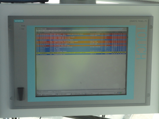
The visualisation is achieved via the service- and information system SIS by POLO. The visualization is represented on SIS-computers in the E-house and in the driver’s cabin. The communication between the PLC and the SIS-computers occurs via Ethernet.

The main purpose of the visualisation is the representation of upcoming error messages. The message includes specific information about the error and facilitates the search for errors. Additionally it shows the parameters of the trolley travel, the hoisting gear and the travelling gear.
Monitoring via failsafe PLCs
Another important feature of this system is the safety concept. The PLC is a failsafe Siemens S7-317F. All safety-relevant functions, such as emergency stop signals, emergency limit switches, overload signals etc. are conducted onto failsafe imputs or outputs respectively.
Why HIT?
HIT have successfully completed this project. A clear user interface was designed for the operators. From the very beginning, this container gantry has proved its reliability. These features have increased the failsafe performance and the productivity of the system.