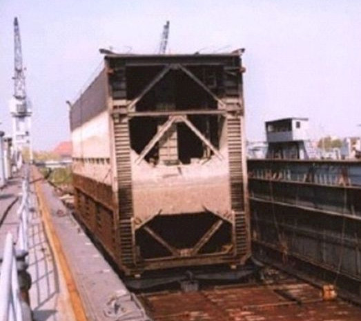
The sea lock comprises two chambers each with a length of 400 m, a width of 60m and a lock bottom that is around 17 m below the mean high tide. The chambers are opened for ships to move in and out by sliding gates that are 60 m long, 10 m wide, 20 m tall and weigh 1700 t. The gates are mounted using the wheelbarrow system on carriages at the top and bottom. The gates are driven by electric motors controlled by frequency converters. It takes five minutes to completely open or close the gate.
Water levelling is brought about by roller-guided gate contactors. The seals are formed by two folding roller gates each located in the centre and equipped with hydraulic lifting cylinders. The time to fill or drain the lock chambers is around 16 minutes during an average lifting of the lock. The gates are sealed by hardwood at the upright stops and at the lock sill.
The lock gates, the contacts and the signals are operated and monitored by a central control station that is located in the operations building on the island of the lock.
The drive technology

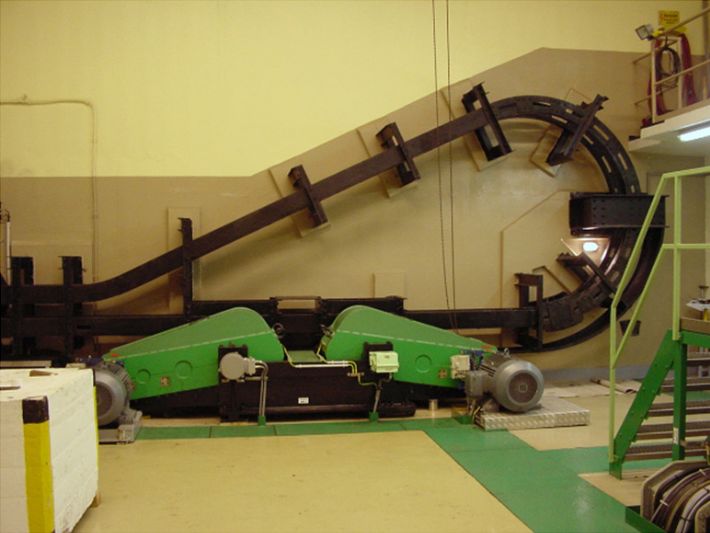
Each of the lock’s sliding gates, which have a mass of approx. 7300 t to accelerate, is moved by four three-phase current industrial motors, AEG AMV S 280/45 kW, via elastic split couplings, mechanical transmissions and lantern gear chains. All the drive motors are controlled synchronously by frequency converters, AEG Miniverter-D 73/380. In the limit positions, the gates are held by four drum brakes each, driven by EMG-ELDRO units ED 23/5.
The controls

Originally, the entire lock system was controlled using four PLCs type MODICON A350. Since then one of the two chambers, the west chamber, has been modernised. For each gate of the chamber, one PLC Simatic S7-412 is now used. With decentralised peripheries in the lock gates, in the form of ET200 stations, the cabling complexity has been considerably reduced.
In this vast system, all the components are interconnected via an extensive optical waveguide network. The connection to the controls is provided via Ethernet and the cross-coupling between the two gates via a Profibus DP.
The PLC program is modular and has been implemented entirely in the programming language SCL. It is portable to the individual lock heads. This procedure ensures optimum maintenance and allows additions to be made flexibly and reliably. If maintenance is needed, we can provide help at your request via a modem link – with flexibility and without delay.
The control station

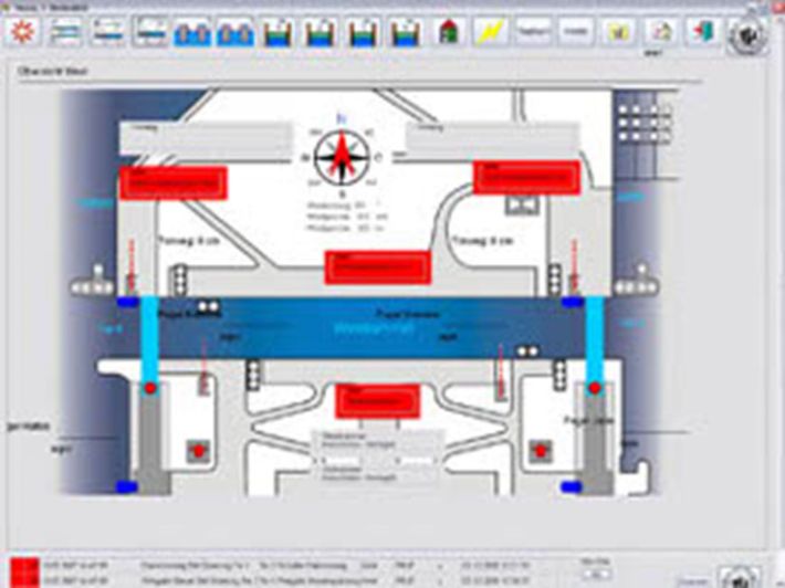
Depending on the client’s wishes, the operation can also be achieved via WinCC, a Siemens product. The opening and closing of doors is signalled graphically. Current machine data, like power consumption, temperature, weight and operating states of the machine are displayed on the visualization images and recorded simultaneously. The recording of temperature charts, currents patterns etc., is part of the equipment, as is the graphic signalling of error messages. All alert messages are recorded in a history file and can be called up at a later date.
Why HIT?
HIT successfully completed this modernization. A clear user interface was designed for the operators and a good system and software structure was created for the service team. From the very beginning, the system proved its reliability. These features increase the failsafe performance and the productivity of the system.